METEOR87 (ECU ONLY)
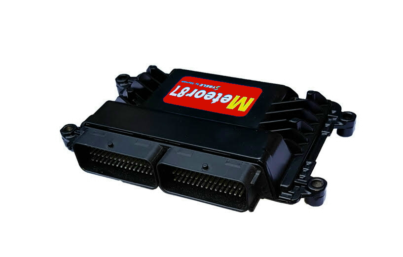
The Meteor87 is designed for those who truly seek the Win. Its speed and its computing power allow astonishing accelerations. From 1 to 6-cylinder in sequential, and 8 to 12-cylinder in semi-sequential. Evolved strategies of control allow an effective protection of the engine . Complete flexfuel management with Ethanol content sensor . Machine gun Hard cut limiter with burst of flames .
The Meteor87 is designed for those who want an exceptional ECU. It allows managing from 1 to 6-cylinder engines in sequential injection and static ignition, and 8 to 12-cylinder engines in semi-sequential injection and lost sparks ignition. It can manage engines in line and ‘V’ engines as well, with a separated management for each bank of cylinders (intake, Lambda, turbos, fly by wire and camshafts for each bank).
Thanks to its high performance microprocessor and its multiple possibilities the Meteor87 allows to get astonishing accelerations by a total engine optimization.
The Meteor87 owns the same features than the Meteor86
• The difference between the two is that the Meteor87 has an auxiliary Peak and Hold command. This command allows a better management of devices with high current command, such as fuel high pressure pumps for direct injection.
Several tunings can get along for the same engine (multimapping). The desired tuning can be selected while running, by a rotator or a dashboard switch, allowing the adaptation to the driving conditions, a super boost of the engine if necessary.
Complete management of the flexfuel with reading of Ethanol content sensor
• Sensor reading inhibition if the fuel flow passing through the sensor is insufficient for a correct reading of the Ethanol content
• Correction of injected quantity according to Ethanol content, engine t°, engine load and engine speed
• Ignition advance correction based on Ethanol content, engine t°, engine load and engine speed
• Specific injected quantity at engine starting according to the Ethanol content and the engine t°
• Specific ignition advance at engine starting according to the Ethanol content and the engine t°
• Specific richness target according to the Ethanol content and the engine load
• Specific turbo pressure and turbo speed targets according to the Ethanol content
• If you need it, Skynam can provide the Ethanol content sensor
A full self-learning function allows the ECU to auto tune its injection time map when equipped with a wide band Lambda sensor (integrated with the standard license).
The Meteor87 also manages direct injection if is added a DDi08 high voltage injectors driver.
Direct injection is the specialty of the Meteor87.
TECHNICAL PRESENTATION
CONFIGURATION
• 6 injection channels (sequential injection, semi sequential or direct)
• 6 ignition channels (static ignition or lost spark)
• 13 fully programmable auxiliary outputs including one Peak and Hold output (the outputs are used for the flies by wire management, proportional camshafts drift, FISA regulation fuel pump, etc …)
• 1 RPM sensor selectable Hall effect or inductive on crankshaft flywheel
• 1 Main phase sensor selectable Hall effect or inductive on camshaft flywheel
• 3 Auxiliary phase sensors selectable Hall effect or inductive on camshaft flywheel of which 2 are shared with the speed inputs
• 1 internal power supply tension measurement
• 5 logical input type on-off switch
• 3 resistive inputs NTC-PTC-PT200 or logical
• 3 analogic 0-5 volts inputs
• 8 selectionnable analogic-resistive inputs
• 2 knock sensors inputs with differential measurement
• 2 speed inputs Hall effect or magneto resistive, number of teeth from 1 to 128
• 16 CAN-Bus inputs (for example switches or rotators provided by the dashboard)
HELP IN THE SETTING
For a fast tuning, the maps of engine start, engine temperature rise, accelerating pumps and atmospheric altimetric pressure and intake t° corrections are preset for the ignition advance as for the injection.
The PID of devices commands (motorized throttles, turbo, fuel pressure) are also preset.
ADVANCED FUNCTIONS OF ENGINE MANAGEMENT
Very advanced engine management functions allow a total optimization of the engine working:
• Cylinder by cylinder correction of injection and ignition
• Assignment cylinder bank by bank for ‘V’ engines
• Correction of richness by wideband Lambda sensor specific for each cylinders bank
• Capability to use one intake pressure and one throttle (motorized) per cylinders bank
• Operation in two injection rails with gradual shifting from one to the other
• Proportional positioning of camshafts (VVT)
• Fuel pressure management
• Injection correction by fuel pressure
• Management of the motorized throttles (with specific tuning allowed by gear position)
• Direct injection engine management (see direct injection kits)
• Multi fuels and additive management
• Complete management of flex fuel (Ethanol)
ADVANCED FUNCTIONS OF RPM LIMITER AND LAUNCH PROCEDURE
• Rpm limiter on injection or ignition or both together or one after the other
• Modifiable rpm limiters following gear position, intake temperature or engine temperature or elapsed time in limiter
• Soft cut or Hard cut limiters selectable
• Several launch limiter and race limiters, selectable by a rotator (rotary switch) at the vehicle board
• The different launch limiters allow to adapt to the road grip conditions
• Tunable gradual limiter raising from launch limiter to race limiter to avoid wheels slipping at vehicle take-off
• Injection time and ignition advance correction during launch procedure to get high turbo pressure for a cannonball take off
• Soft cut limiter: gradual cylinder per cylinder cutoff, and turning (always begins the cutoff sessions with a different cylinder to avoid always heating the same cylinder)
• Hard cut limiter: all the cylinders are cutoff at the same time, with tunable hysteresis to uncut the cylinders with tunable modification of ignition advance and injection time for a machine gun limiter with burst of flames
ADVANCED FUNCTIONS OF GEARBOX MANAGEMENT
Sequential gearbox management or specific management of robotized gearbox or road gearbox.
• Logical or analog switch (strain gauge) with definition of the triggering thresholds
• The order of gears can be automotive type or special
• Intervention time in function of gear position, rpm and engine torque
• Intervention at gear upshift on ignition by cutoff and/or advance modification with slope of return to normal (transmissions protection generating bang and exhaust flame)
• Programmable engine automatic acceleration (blip) and ignition cutoff at downshift
ADVANCED FUNCTION OF CAMSHAFTS POSITIONNING
The proportional positioning can be made on one or two camshafts per bank.
• 4 intake and exhaust camshafts for ‘V’ engines
• 2 intake and exhaust camshaft for in-line engines
The proportional positioning is executed in PWM with
• 1 electrovalve for each camshaft for standard management
• 2 electrovalves for each camshaft for BMW M3 type management (one for advancing and one for delaying)*
The camshafts targets can be:
• on mark state
• on mark position
• on one missing tooth
• on one supplementary tooth
• on regular teeth (exhaust only)
ADVANCED FUNCTIONS OF TURBO MANAGEMENT
The turbo management is made by the PWM command of a pneumatic electrovalve of leak or a servo-motor. Wastegates with back pressure are also managed.
• 1 turbo
• 2 twin turbos in parallel (1 by bank of cylinders)
• 2 sequential turbos in parallel
• 2 staged sequential turbos
• 3 turbos, with two in parallel and the third serial with both first ones
Turbos in sequential mode are started only under selectable conditions.
• Turbo management in pressure or in turbo rpm or both with dynamic choice of the type of management.
• For ‘V’ engines with intake separated by bank, it is possible to read 2 pressure sensors, each allocated to a bank of cylinder, to manage each of the twin turbos with its own pressure.
• Turbo protection by turbo rpm limitation
• Management of wastegates with back pressure
• Pressure and turbo rpm target tunable according to gear position, exhaust or intake or engine temperature, altimetric pressure, Ethanol content
• Bang-bang (antilag system) managed with fly by wire, proportionnal air electrovalve or mecanical throttle opening device
• Bang-bang at the starting up for cannonball launch
• Bang-bang monitoring by exhaust temperature
• Bang-bang disabling by dashboard switch for road driving
• Programmable injection of water
ADVANCED FUNCTIONS OF DIRECT INJECTION MANAGEMENT
See Direct injection kit.
ADVANCED FUNCTIONS OF ENGINE PROTECTION
• Programmable reaction (by limitation of torque, rpm, or engine cutoff) on problem of oil pressure, fuel pressure, engine temperature, oil temperature, turbo pressure, … with alarm lights and recording of the faults
ADVANCED VEHICLE MANAGEMENT
• Traction control
• Vehicle speed limitation (rallye raid, pitlane, …)
ADVANCED ENGINE MEASUREMENTS
• Every measure has a customizable digital filtering
• Every measure maybe assigned in a selectable way to a physical input of the ECU, to a calculated value (ie double potentiometers)
• For every measure of the ECU, it is possible to define a strategy of detection of failure, a strategy of replacement value in case of failure, or to use the standard strategies supplied by the ECU
• Turbo speed, wheels speed
• Wideband Lambda sensors
• Oil pressure, fuel pressure, oil t°
• Exhaust temperature by thermocouple module or PT200
ADVANCED PROGRAMMABLE STRATEGIES
Extremely flexible and simply programmable strategies allow the motorist to multiply the possibilities of tuning
The use of these advanced functions and the development of specific strategies does not require either the learning or the knowledge of a programming language. The innovative and natural technique, called SKYMCOD Mapped programming, developed by Skynam, performs this role.
For example,
• Several selectable possible engine tuning by rotator or by quite other condition chosen by the motorist (for example multi fuels with programmable switching, additives)
• Addition of engine devices (intake flaps, exhaust throttle)
• Programmable auxiliary inputs for new measurements creation
• Management of restrictor pressure for overboost engines
• Programmable injection of water
• The ECU can react to the oil temperature or to the oil pressure according to the rpm or to quite other parameter or the combination wished to control, activating alarms or switching off the engine, or changing the strategies of injection, ignition, overboost, command of the motorized throttle, or other
• The motorist can intercept all the targets of the ECU (injection, ignition, turbo pressure, bang-bang, fuel high pressure, proportional positioning of camshaft, richness correction, rpm limiter, motorized throttle) and modify them with his appropriate strategies
AUXILIARY CAN-BUS
Two completely programmable auxiliary CAN-BUSes (11 and 29 bit identifiers, speed until 1 Mbits) allow to exchange data with the others connected nodes, car manufacturer devices or data recording or dashboard. The received data can be used in the advanced functions of calculations and developments of strategies.
AUXILIARY OUTPUTS
13 completely programmable auxiliary outputs.
They can be configured in On-Off (programmable hysteresis), PWM from 10 to 10000 Hz or angular or engine synchronous phased commands, with adjustable cyclical ratio (and phase), and controled by any combination of parameters known by the ECU, including the values received from the auxiliary CAN-BUSes, and or from the sophisticated strategies developed by the motorist and fully configurable PIDs.
One of these auxiliary outputs is in Peak and Hold command. This type of command allows a better management of devices with high current command, such as fuel high pressure pumps for direct injection.
The Peak and Hold command is composed of two parts, during which the voltage is supplied by the engine 12 volts battery supply with current control by switching the battery power:
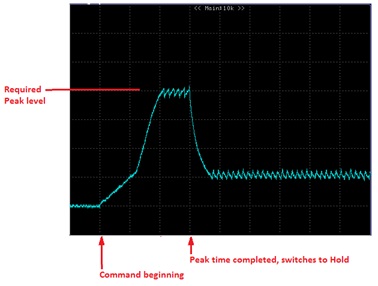
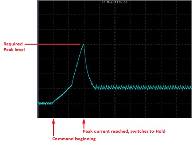
The Peak delivers a strong current for a few hundred microseconds. This peak is a necessary part for a very fast opening of the solenoid valve. Two peak command types are allowed:
1) The ECU controls the current during all the Peak time then switches to the Hold.

2) The ECU switches to the Hold as soon as the Peak current is reached. The Peak time is the maximum duration before the command switches to Hold, in the case where the desired current is not reached (for example if the battery tension is too low).

In both cases, the Hold maintains the opening of the solenoid valve without damaging it by an excessive rise of its coil temperature (lower level of current).


